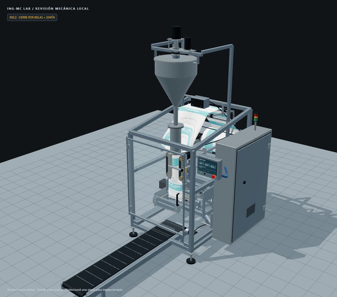
A jaw animation may look plausible while its connecting rods stretch or the two jaws drift away from the forming tube. This guide follows the actual R02.2 mechanism and the checks used to keep its browser motion geometrically connected. The dimensions are estimated concept geometry, not a machine specification.
Start with the force path
The model uses one servo/reduction envelope to turn a common keyed shaft. Mirrored levers on that shaft drive four fixed-length rods. The rods move the rear jaw and a return plate linked to the front jaw; tie rods guide the rear carriage. A separate actuator moves the knife, which rides with the rear jaw and retracts before the jaws open.
That arrangement is one possible intermittent cross-seal architecture, not a universal VFFS layout. ROVEMA describes a servo-based main drive for the cross-sealing station on its BVI series; Syntegon describes four independently controlled servo motors in the SVX cross-seal drive. Those manufacturer descriptions are useful context, but their geometry, force and output figures do not transfer to this ING-MC concept.
Reconstruct the rod position
Let r be the crank radius, L the pin-to-pin rod length and θ the crank angle measured from the horizontal. The solver finds the rod endpoint’s horizontal reach D from the shaft axis:
D(θ) = r cos(θ) + √(L² − (r sin(θ))²)For R02.2, r = 75 mm and L = 325 mm. At the modeled closed position, θ = 12° and D ≈ 398 mm. At the open end, θ ≈ 108.794° and D ≈ 293 mm. The reach changes by 105 mm; the mirrored jaw coordinates preserve the forming-tube center, so each jaw travels 105 mm in the model. The recorded face gap changes from 212 mm open to a nominal 2 mm closed around the represented film.
The 12° closing position remains before dead centre. It avoids switching the linkage to the other geometric branch in this animation; it does not establish an over-centre lock or a usable sealing force. Approaching dead centre makes the motion ratio sensitive to geometry, compliance and backlash. Motor torque, reduction efficiency, bearing loads and jaw force need separate calculations using selected hardware and process loads.
What the motion checks establish
The pose solver recalculates the crank pins and rod ends at every requested position rather than independently interpolating two jaw meshes. The automated geometry check samples 181 positions from open to closed and verifies that all four rods remain 325 mm long, both jaw centers stay symmetric about the tube axis and the crank remains on the intended side of dead centre. The recorded numerical closure error is at floating-point scale; it is not a fabrication tolerance.
In the interactive VFFS viewer, run the cycle or step through its phases, then select Jaw transmission · section. Inspect both sides of the shaft, the return plate, guide rods and knife. Check the fully open and closed poses as well as intermediate motion; one attractive isometric frame cannot reveal a link that disconnects halfway through a stroke.
What a production design still needs
Before sizing a real station, establish the actual film stack and seal process, required force and dwell, target cycle rate, drive and reducer data, shaft and bearing reactions, frame deflection, joint clearances, wear and full swept-volume interference. The viewer’s 105 mm travel and 2 mm nominal gap are useful for reviewing this concept only. They are not proof of seal quality, machine capacity, safety or manufacturability.
For the material and timing sequence, continue with the VFFS film-sealing guide. For the broader sequence-state distinction, see PLC recovery after a stop.