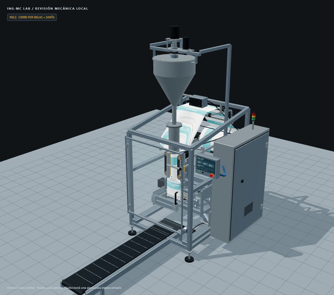
A vertical form-fill-seal machine begins with a flat web of film and turns it into a package around a forming tube. To understand the cycle, follow the material and distinguish continuous geometry from timed actions. The interactive ING-MC bagger illustrates that relationship with an auger doser and mechanically coupled transverse jaws.
Follow the material path
Film travels from the rear roll through guides toward the forming collar. The collar reshapes the flat web around one hollow tube. Pull belts advance it downward; the longitudinal sealer closes the overlapping edges. Transverse jaws form the bag’s horizontal seals, and a knife separates the completed package before discharge.
The current R02.2 model includes one forming tube, an auger doser and an independently driven coaxial agitator. The auger turns during dosing with the film stationary. Its displayed turns and visual powder load are illustrative, not a measured mass or a calibrated feeding system; no multihead weigher is represented.
Why intermittent timing matters
An intermittent illustration separates advance from transverse sealing. The film advances while the jaws are open. During closure, sealing and cutting, the pull motion must not continue as if nothing changed. The representation then opens the jaws before releasing the package.
| Visual phase | What to inspect |
|---|---|
| Fill | Material stays below the intended seal zone |
| Draw | Film and pull-belt motion agree |
| Close/seal | Jaws meet the film; advance is paused |
| Cut | Separation occurs within the represented knife path |
| Open/release | Jaws clear before bag discharge |
The table explains the conceptual sequence, not a controller program. Temperature, dwell, pressure, material properties and actual timing must come from the real packaging process and equipment requirements.
Registration and printing are different functions
The registration sensor represents detecting a film mark for positioning. The thermal-transfer overprinter represents variable lot/date coding. The package artwork is already printed on the roll: the model does not show a full-color package printer or a label applicator.
Videojet’s TTO overview describes that coding function. IMA’s intermittent VFFS overview provides machine-category context. The ING-MC illustration is original and does not claim those manufacturers’ geometry, equipment identity or performance.
Static geometry does not contain the complete cycle
The model’s GLB holds fixed geometry and named assemblies. JavaScript supplies deforming film, generated bags, particles, flexible connections and phase motion. Loading only the GLB therefore does not reproduce the complete standalone viewer.
A common keyed shaft drives lever pairs at both ends of the transverse jaws. Four constant-length connecting rods move the rear jaw and the front-jaw return crosshead. The cutter rides on the rear jaw but moves independently and retracts before opening. The closed kinematic chain maintains connected pivots through the visual sweep; it does not calculate bearing loads, drive torque or manufacturing tolerances.
Inspect the cycle in motion
In the interactive VFFS viewer, step through one bag: dosing occurs with the film stopped, the pull belts advance with the jaws open, and the knife retracts before release. For the actual linkage dimensions and geometric closure checks, continue with the four-rod jaw transmission guide.