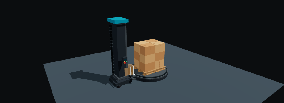
Wrapping is easier to understand when you follow the film rather than only watching the pallet rotate. Open the Stretch Wrapper demo and identify the turntable, mast, carriage and film roll. Each has a different role in the resulting pattern.
Separate rotation from vertical travel
The turntable changes the pallet’s angle relative to the film source. The carriage changes the height at which film reaches the load. Combining rotation and vertical travel creates the rising or descending wrap; holding height while rotating adds passes near the same level.
The visual scene lets you inspect those relationships. It does not prove a physical load is stable or establish the correct number of reinforcing passes. Those choices depend on the load, film and equipment specification.
Read the path one phase at a time
Start a single visual cycle, pause it and use the front or isometric view. Inspect whether the film reaches the current contact height rather than a fixed point left behind in the model. Resume and follow the carriage along the mast.
In this LAB adapter, a full visual cycle takes 36 seconds at 1× playback. The speed setting changes playback, not a rated production speed. Film visibility is independent of the cycle so you can inspect the underlying components without resetting motion.
Reset returns the browser scene to its initial condition. It does not represent a machine homing routine, film attachment or a completed cut-and-clamp operation. Camera controls only affect observation; they do not alter the sequence state.
Coverage depends on two motions
For a simple constant-speed teaching case, if the carriage rises at v millimetres per second and the turntable rotates at n revolutions per minute, vertical travel per revolution is p = 60v / n. With an illustrative v = 10 mm/s and n = 12 rpm, p = 50 mm/revolution.
If the effective film width is assumed to be 500 mm and there is no neck-down, that geometry gives 450 mm of overlap between adjacent passes. This is an idealized calculation, not a film recommendation: actual film width at contact, deformation, corner behavior and speed ramps change coverage.
Use the example to distinguish pitch from film stretch. A visually wider film strip does not prove more material was delivered, and a longer drawn path does not establish consumption.
What the renderer calculates
The model supplies static component geometry and semantic frames. The renderer adds and updates the film representation during the cycle. It converts contact positions into the source model’s frame before rebuilding the visual path, keeping the film aligned when the model is placed within the common viewer’s coordinate system.
This is a geometric visualization. It does not solve film tension, prestretch ratio, force on the load, friction, tearing or measured material usage. GLB geometry alone also does not contain the whole wrapping behavior; runtime logic supplies the moving visual elements.
What a real integration would observe
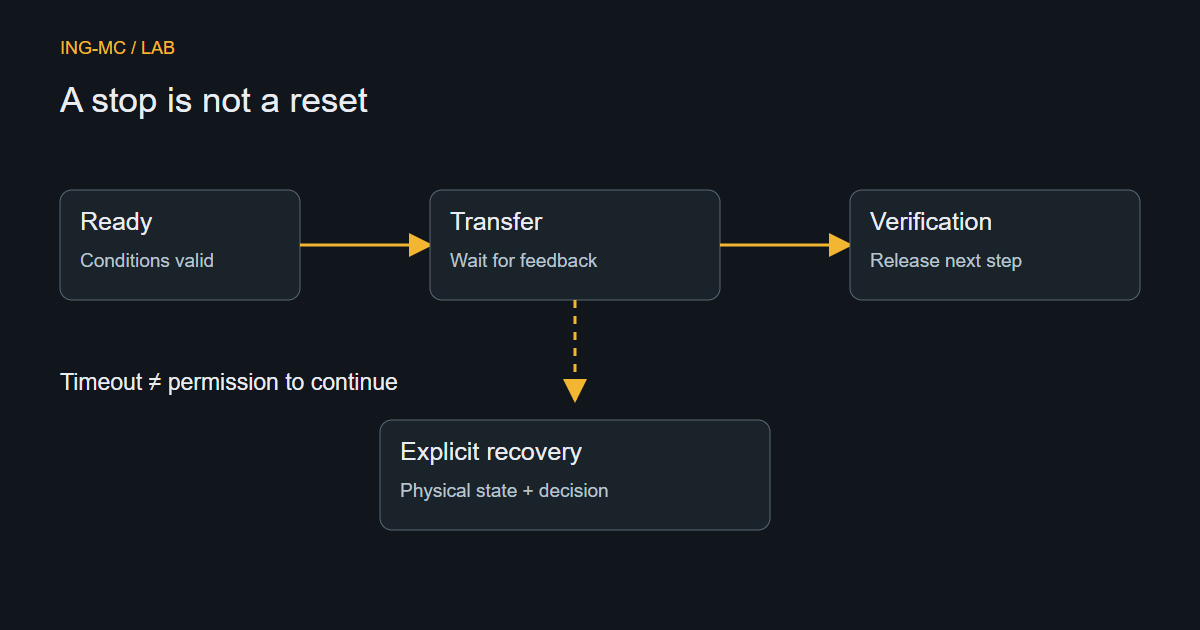
A connected view needs reviewed turntable and carriage positions, machine state, drive readiness and communication quality. The control project needs its own limits, recovery sequence and validated machine protections. If feedback disappears, the view should stop claiming a current wrapping position instead of continuing a plausible-looking animation.
Compare this with PLC recovery states: stopping mid-wrap may leave film and load conditions that Reset cannot infer. Use the demo to discuss the process, then build acceptance checks around the actual signals and equipment—not the browser’s timing.