The client connects, but the temperature is wrong. Before changing byte order or guessing nearby addresses, determine what the manual means by “register.” A human-readable reference and the address transmitted in a Modbus request are different pieces of information.
Register area and address are separate
The Modbus application protocol defines zero-based addresses in the PDU. Function codes select the data operation: FC02 reads discrete inputs, FC03 reads holding registers and FC04 reads input registers. A register contains 16 bits; a discrete input represents one bit.
In a manual using conventional references, holding register 40001 commonly corresponds to FC03 address 0. The leading 4 identifies the area; it is not transmitted as part of the PDU address. Do not subtract 40001 from every vendor number: some manuals already publish zero-based offsets, use hexadecimal addresses or use different notation.
Build an unambiguous mapping sheet
For each signal, record the device/manual revision, area, displayed reference, PDU offset, quantity, type, scale, unit and read/write permission. The following values are deliberately invented for learning, not a PLC configuration:
| Signal | Reference | Operation | PDU offset | Encoding |
|---|---|---|---|---|
| Temperature | 40001 | FC03 read | 0 | unsigned 16-bit, ×0.1 °C |
| Counter | 40002–40003 | FC03 read | 1, quantity 2 | unsigned 32-bit, high word first |
| Input status | 10001 | FC02 read | 0 | one bit |
A raw temperature value 250 means 25.0 °C under this example scale. It does not justify applying ×0.1 to another instrument. Store raw and interpreted readings together during the bench test so you can identify whether a fault comes from addressing or conversion.
Byte order is not the same as word order
Within a Modbus register, the protocol sends the most significant byte first. A value spanning two registers adds a second question: which 16-bit word comes first? That application encoding is device-specific. For example, high-word-first words 0x0001 and 0x0002 represent unsigned 65538; reversing the words produces 131073.
Do not apply the unsigned-integer conversion to a 32-bit float. A float needs the documented IEEE 754 encoding and register order. Likewise, a signed 16-bit value must be interpreted as signed before scaling. Plausible-looking values are not proof that the format is correct.
Validate a response before trusting the value
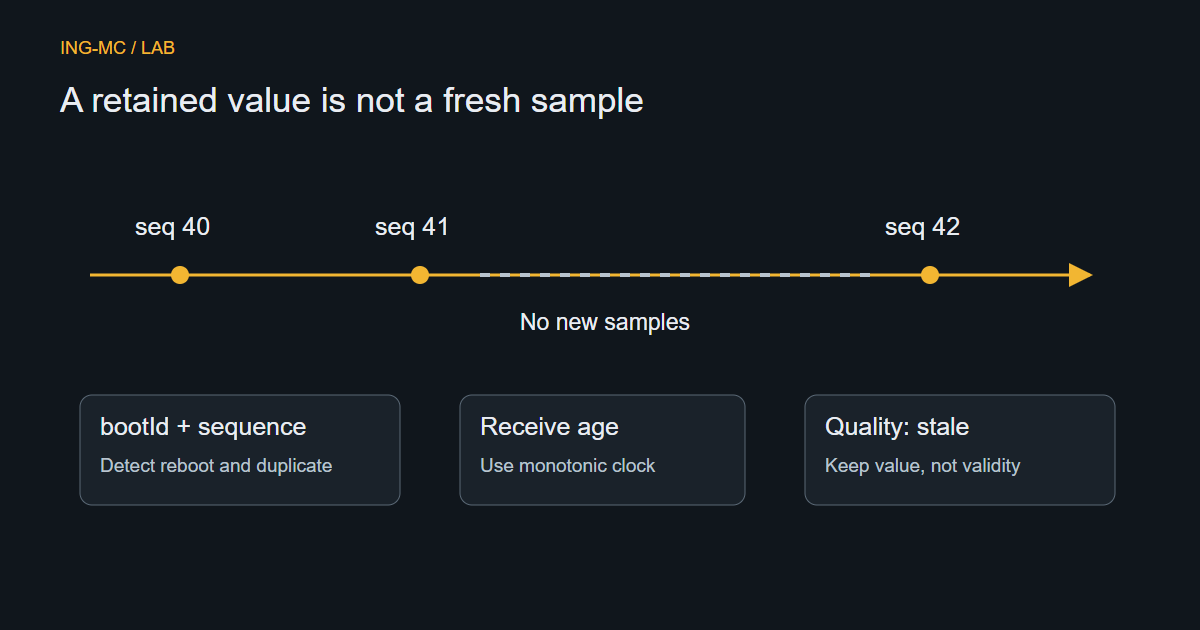
Check the response belongs to the request, has the expected function and payload length, and is not an exception response. A TCP connection does not mean the register read succeeded. A timeout, exception or malformed response should update communication quality; it must not silently replace the process value with zero.
Begin with a small, read-only bench request against a known test value. Compare the device display, raw response and decoded value. Repeat at another known value to catch accidental agreement. Verify the actual Unit Identifier and gateway behavior rather than copying them from an unrelated installation.
Keep diagnosis out of the control path
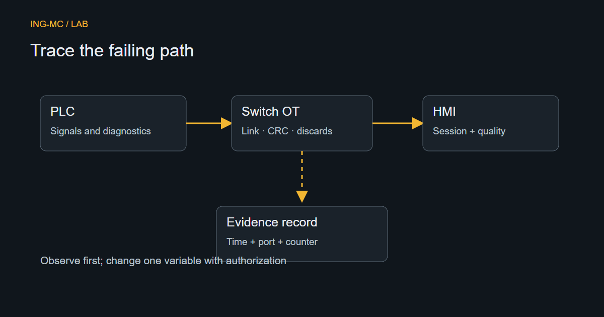
A monitoring application should read only the approved map. Do not probe adjacent registers or issue writes to “see what works” on running equipment. Record request timing and error counts without flooding the controller. If only one device fails, follow the OT diagnosis guide before changing the entire polling configuration.
Keep the approved mapping sheet versioned with the software. A comment saying “address 1” is ambiguous; “FC04, PDU offset 1, one unsigned register, scale 1” can be reviewed and tested.